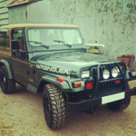
hey jeep looks great, quick question the winch you used is that a superwinch LP8500?
how hard was it to remove the control box?
Thanks
Jack
Colorado JP #29
-
Jack_Fauth

- Completed JP Jeep
- Posts: 330
- Joined: May 13th, 2010, 12:09 pm
- Location: Lancaster Pa
- Contact:
Re: Colorado JP #29
Still selling complete decal/stencil kits in any number
Jeep conversion service http://www.no-limitcustoms.com
95 Sahara- PA Jeep#12-SOLD
000 _oooo_
00/| ,[___],
|--L@/--[]lllll[]-
()_) 0 ()_)-o-)_)
Jeep conversion service http://www.no-limitcustoms.com
95 Sahara- PA Jeep#12-SOLD
000 _oooo_
00/| ,[___],
|--L@/--[]lllll[]-
()_) 0 ()_)-o-)_)

Re: Colorado JP #29
yes it is a superwinch lp8500.
Removing the control box (solenoid) wasn't too bad. (obviously disconnect battery/winch before starting)
First remove the 4 screws in the plastic box to get access to the inside of the box. The top half of the plastic box has the wires for the remote, so it comes off, but can only be moved out of the way unless you want to unwire the remote wires. You do not need to unwire the remote wires, it gives you enough access that you can get the rest of the stuff undone.
Second: with the top loose enough to access the internals you will have to unbolt the power bars. The winch has 3 SOLID Copper power bars that connect the solenoid to the winch motor. They are about 1/8 in thick solid BARS. Unbolt these three bars.
Third: There is a small black ground cable that goes from the solenoid down to the winch's motor ground. This is held on by 1 screw on the solenoid and bolted along with the main ground cable to the bottom of the winch. Remove this cable.
Fourth: with all the wiring disconnected the box's lower half is connected to the winch with two brackets which are screwed to the box with 2 screws each and 1 screw each into the winch body. Remove the 2 screws into the winch body with a long screw driver.
The box should now be free to be removed from the winch. Then I removed the 2 mounting brackets from the box.
I choose to make new brackets that screwed into the existing holes in the bottom portion of the box, but you might could bend/adjust the brackets if you wanted. They aren't super thick.
Re wiring: You will need 3 - 2 gauge wires to reconnect the box to the winch, and one 12ish gauge ground cable. I choose to also replace the positive main cable that came with the winch since the new location was so much closer to the battery, instead of having extra cable coiled in the engine compartment. So I got 4 - 2 Gauge cables, All four cable based on MY LOCATION were 42" long. Measure VERY carefully if you have cables made you don't want to be short, BUT you also don't want to coiled a bunch of 2 gauge wire either!!!! Plus the shorter the cable runs the better electrically you are making the circuit.
From the solenoid to the winch are 1 "positive" red cable (this is actually I beleive called F1 and is "white") and 2 "other" cables (one "yellow" and one "green" (F2 and F3 technically I believe), I used black with colored electric tape at each end to differentiate, I doubt you could find battery cables in anything other than red and black, but I didn't look real hard). Connect the cables to the same terminals that the bars were connected to originally, making sure to connect the correct lug on the solenoid with the correct lug on the winch motor. (pretty easy once you see how they are laid out when you start taking it all apart, but make a diagram if you are concerned about getting them right) The "positive" one has to be correct, or you will short something out. If you swap the "green/yellow" cables then the remote will work in reverse. The small (12 gauge) ground from the solenoid that you removed earlier needs to be connected to a ground. I choose to run this to the battery ground terminal itself as that was cleaner than running a 5th cable to the winch ground point where it was originally connected. (it was originally connected to the winch ground lug, which is directly connected to the battery ground terminal via the original main negative run, so I just went straight to the terminal.) Though you could probably run this to any vehicle ground as well.
1993 Sahara - JP29 - Denver, CO
Re: Colorado JP #29
updates.. I went no expense spared with my electrical.... 
I am wiring up the rear fogs, redoing the wiring for my front fogs so they are independent of the headlight switch, and wiring up remote winch controls in the dash...
The stock fog light switch (and rear defrost switch if you had a hard top) are located in a panel at the lower right of the steering wheel. This panel has 3 cutouts already waiting for switches... So I took apart the dash to remove that panel, and opened up the 2 additional switch locations. I am installed Contura Laser Etched switches (no expense spared )
So far I have completed the switch install, but need to wire them up. I will be stopping at radio shack today to get a 9 pin male and female plug to make future servicing easier.
I also completed the wiring of the rear fogs through the lights/body. I did the following. (mine are 1 wire lights) My fog light lugs are bolted to the grounding plate in the rear housing. I did Not want to drill a hole in the body for the supply wire, so I took apart the rear lights and fed a supply line through the rear light supply. Then I zip tied it to the existing lines to keep it away from the bulbs. NOTE I used high quality GXL automotive wire, which is rated for high temps, not the cheap unknown wire that came with my light kit. I drilled a hole out the light and used a rubber grommet in the hole, with the wire fed through this, to keep the light water resistant, and to protect the wire from chaffing. The grommet I used was a solid grommet with NO center hole, I drilled a center hole smaller than the wire so it should be relatively water tight. Between this wire and the fog light is a quick disconnect, so if I need to remove the fog light from the taillight I can.
The wiring "tube" that the stock lights have is crimped at the end, so you can not get the wire to come out there. I used a knife and cut a slit along the tube right near the end, when I got the wire pushed through, I just pulled it out the new slit I added. I added a quick discconect here, so I can still remove the whole light housing by unplugging the stock harness and my fog light wire.
(So I can now remove only the fog if I need to, or the whole rear tail light assembly including the fog if I need to)
I used a coat hanger to guide my new wire for the passenger side light through the wiring loom above the gas tank. At the driver rear corner I put the double disconnect that came with my kit to join both feed that is now in the wiring loom from the passenger side, and the feed coming from the driver side light. I drilled a hole through the body grommet that feed the existing light wiring to get my power wire into inside of the jeep.
I still need to feed the power wire of the fogs into the loom from the back corner up to under the dash. Where I am doing the rest of teh wiring... Pictures and more details to follow as I get it completed.
I am wiring up the rear fogs, redoing the wiring for my front fogs so they are independent of the headlight switch, and wiring up remote winch controls in the dash...
The stock fog light switch (and rear defrost switch if you had a hard top) are located in a panel at the lower right of the steering wheel. This panel has 3 cutouts already waiting for switches... So I took apart the dash to remove that panel, and opened up the 2 additional switch locations. I am installed Contura Laser Etched switches (no expense spared
So far I have completed the switch install, but need to wire them up. I will be stopping at radio shack today to get a 9 pin male and female plug to make future servicing easier.
I also completed the wiring of the rear fogs through the lights/body. I did the following. (mine are 1 wire lights) My fog light lugs are bolted to the grounding plate in the rear housing. I did Not want to drill a hole in the body for the supply wire, so I took apart the rear lights and fed a supply line through the rear light supply. Then I zip tied it to the existing lines to keep it away from the bulbs. NOTE I used high quality GXL automotive wire, which is rated for high temps, not the cheap unknown wire that came with my light kit. I drilled a hole out the light and used a rubber grommet in the hole, with the wire fed through this, to keep the light water resistant, and to protect the wire from chaffing. The grommet I used was a solid grommet with NO center hole, I drilled a center hole smaller than the wire so it should be relatively water tight. Between this wire and the fog light is a quick disconnect, so if I need to remove the fog light from the taillight I can.
The wiring "tube" that the stock lights have is crimped at the end, so you can not get the wire to come out there. I used a knife and cut a slit along the tube right near the end, when I got the wire pushed through, I just pulled it out the new slit I added. I added a quick discconect here, so I can still remove the whole light housing by unplugging the stock harness and my fog light wire.
(So I can now remove only the fog if I need to, or the whole rear tail light assembly including the fog if I need to)
I used a coat hanger to guide my new wire for the passenger side light through the wiring loom above the gas tank. At the driver rear corner I put the double disconnect that came with my kit to join both feed that is now in the wiring loom from the passenger side, and the feed coming from the driver side light. I drilled a hole through the body grommet that feed the existing light wiring to get my power wire into inside of the jeep.
I still need to feed the power wire of the fogs into the loom from the back corner up to under the dash. Where I am doing the rest of teh wiring... Pictures and more details to follow as I get it completed.
1993 Sahara - JP29 - Denver, CO
Re: Colorado JP #29
Ok spent the day getting all wiring to the proper locations, installing split loom in the engine bay, and getting everything organized, then plugging in my harness, and Bam all working!
Here are the switches all Installed.. ignore the dusty jeep, it needs a cleaning!!!!
And here they are with the dash lights on. Sweet!!!
And here are the rear fogs lit up!
The switches are all Contura Marine laser etched Switches by Carling. I ordered them from a place called Over the River and Through the Woods or otrattw.com. You can get a TON of switches from them, and they will even do custom work.... I almost thought about seeing what it would cost to do the rear fogs as "Dino Lights" but decided not to. The switches also have an indicator light on them for when they are on. (I should have taken a pic with one switch on and one off.. ohh well. The Winch switch is a momentary switch, so you have to hold it. I choose amber as the led color, but you could choose a bunch of different ones.
I also wired in a winch cut off switch , so to use the winch you have to turn it on, before either the in dash switch or the remote will work. So no accidental winch usage.
No expense spared, all of the wiring is either bundled into existing wire looms or has new wire looms on it.
I wired the front fogs INDEPENDENT of the headlight switch. the stock wiring the front fogs can only be used when the headlights are on low beams, NOT when they are off OR when they are on high. So now the front fogs can be used anytime, no matter what is going on with the headlights. To do this, the switch needed ingition power (which my other switches needed anyway, so I already had it there), instead of the power feed from the headlight switch. I utilized the stock wiring, except the power. The stock fog light switch has 3 inputs, headlight power feed, power out to the fog relay, and ground. I utilized the stock ground as the ground for the whole switch cluster, and used the power out to the fog relay, and just covered the now unused headlight switched power.
My final harness had 7 leads required
Ignition power - I tapped into the radio switched feed as it was handy back there
Dash Light power - The back of the headlight switch has a wire that feeds the dash relay, I tapped into this. The manual says it is blue with red strip, but mine was black with a yellow strip. The manual did show the connector and what was where in the connector, and the wire was in the correct place in the connector.
Front Fog control wire (low voltage) - feeds relay
Rear Fog control wire (low voltage) - feeds relay
Winch In control wire (low voltage) - feeds winch solenoid
Winch Out control wire (low voltage) - feeds winch solenoid
Ground
Here are the switches all Installed.. ignore the dusty jeep, it needs a cleaning!!!!
- Switches Installed
- switches.JPG (146.81 KiB) Viewed 15418 times
- Switches Lit Up
- litswitches.JPG (69.06 KiB) Viewed 15418 times
- Rear Fog Lights
- rearfogs.JPG (112 KiB) Viewed 15418 times
I also wired in a winch cut off switch , so to use the winch you have to turn it on, before either the in dash switch or the remote will work. So no accidental winch usage.
No expense spared, all of the wiring is either bundled into existing wire looms or has new wire looms on it.
I wired the front fogs INDEPENDENT of the headlight switch. the stock wiring the front fogs can only be used when the headlights are on low beams, NOT when they are off OR when they are on high. So now the front fogs can be used anytime, no matter what is going on with the headlights. To do this, the switch needed ingition power (which my other switches needed anyway, so I already had it there), instead of the power feed from the headlight switch. I utilized the stock wiring, except the power. The stock fog light switch has 3 inputs, headlight power feed, power out to the fog relay, and ground. I utilized the stock ground as the ground for the whole switch cluster, and used the power out to the fog relay, and just covered the now unused headlight switched power.
My final harness had 7 leads required
Ignition power - I tapped into the radio switched feed as it was handy back there
Dash Light power - The back of the headlight switch has a wire that feeds the dash relay, I tapped into this. The manual says it is blue with red strip, but mine was black with a yellow strip. The manual did show the connector and what was where in the connector, and the wire was in the correct place in the connector.
Front Fog control wire (low voltage) - feeds relay
Rear Fog control wire (low voltage) - feeds relay
Winch In control wire (low voltage) - feeds winch solenoid
Winch Out control wire (low voltage) - feeds winch solenoid
Ground
1993 Sahara - JP29 - Denver, CO

Re: Colorado JP #29
Those switches look awesome!
1971 Volkwagen Beetle - 1993 Jeep Wrangler Sahara - 1998 Dodge Neon R/T
http://www.GBFans.com/ - http://www.JurassicJeep.com/
http://www.GBFans.com/ - http://www.JurassicJeep.com/
-
ImperialTrooper

- Site Administrator
- Posts: 882
- Joined: July 12th, 2010, 6:32 am
- Location: Las Vegas, NV
- Contact:
Re: Colorado JP #29
You forgot to post the pic of how clean of a wiring job you did, that is the most impressive part to me.
Re: Colorado JP #29
Ok... Here are the harness pics
First the harness behind the switches... Its all low voltage so all 18 GXL auto wire, 7 inputs wires, but lots of connections across the 3 switches, a 9 pin plug, which i got at radio shack.
Next the new loom in the engine bay. The wires exit the firewall through the rubber plug the stock engine harness goes through. Then follows the massiv wire loom along the top back of the engine bay going from right to left in the picture, till it gets over the battery. Above the battery is the new relay for the rear lights (just below the radiator support bar). The wires then follow the left edge of the engine bay (pic 2) and proceed up to the solenoid box (which I had already remote mounted last year)
PS the new loom is the small one that looks ultra black
First the harness behind the switches... Its all low voltage so all 18 GXL auto wire, 7 inputs wires, but lots of connections across the 3 switches, a 9 pin plug, which i got at radio shack.
- SwitchHarness.jpg (86.45 KiB) Viewed 15404 times
- enginebay1.JPG (141.02 KiB) Viewed 15404 times
- enginebay2.JPG (142.32 KiB) Viewed 15404 times
1993 Sahara - JP29 - Denver, CO
-
weapon lxxxi
- Posts: 456
- Joined: October 4th, 2011, 12:29 pm
- Location: South coast UK
- Contact:
Re: Colorado JP #29
Very nice job well done sir!

Re: Colorado JP #29
The only thing I HATE doing is electrical...I dont know alot about this and I am ultra scared of my jeep catching fire..(lot's of these stories online).I always have an extinguisher in my jeeps lolll..it's 30 bucks that could save my jeep..
Re: Colorado JP #29
Basically if you look up a awg auto wire chart, it will tell you what gauge wire to use for the distance you are running and the amps going through it.
For instance the rear fog lights are basically 10 amps. The wire I ran was roughly 25' long for them. (actually shorter, since it was like 15' before the split to go to each light, and after the split it is only pulling half that many amps. But always err on the side of caution) So if I look at the wire chart for awg automtive wire, it says 25' to use a 16 gauge wire. Go up 1 size for safety. So for my rear lights I ran 14 gauge wire. (I also use only Automotive GXL wire, not the standard wire you find everywhere).
Of course you need to figure out the circuit as well.
A standard circuit Looks Like this: http://www.offroaders.com/info/tech-cor ... iagram.gif (ignore the amp ratings on this as it was drawn with higher powered fog lights than I am using.)
Technically you can run the wire without a relay, if your switch can handle the current load. However relays are an extra level of safety. The nice thing also about using relays is the "control wires" are very low amp, and you can use lower gauge wire on them , as they carry 1 amp or less. For instance when I measured the amp load of my winch solenoid's control wire it was 1.3 amps. The amp draw on most relay control wires is way lower! Like 0.16 amps on old bosch relays.
Using lower gauge wire is easier to run, takes up less space, and costs way less! So if you were running wires for front fogs, you would only need higher gauge wire from the battery to the relay to the fogs, and if you put the relay in between the battery and the fogs(physically), you have minimized the amount of higher gauge wire you have to use.
1993 Sahara - JP29 - Denver, CO
Who is online
Users browsing this forum: No registered users and 59 guests